
Introduction of Relay
A relay is an electrical control device. It has a control system (also known as input loop) and a quilt The interaction between control systems (also known as output loops). Usually applied to the control of automation

The relay coil is represented in the circuit by a long box symbol, and if the relay has two coils, two long boxes are drawn side by side. At the same time, mark the relay word symbol "J" in or beside the long box. There are two ways to represent the contacts of relays: one is to draw them directly on one side of the long box, which is more intuitive. The other is to draw each contact into its own control circuit according to the needs of the circuit connection. Usually, the contact of the same relay and the coil side are marked with the same text symbol, and the contact group is numbered to show the difference.
Self-locking and interlocking are achieved by auxiliary contacts of relays. First of all, you need to understand what is called self-locking and what is called interlocking. Self-locking is to short off the button switch of the contactor coil loop with your own contacts, and make the coil loop open continuously after the button switch is released, which is self-locking.

Usage of current transformers
A transformer is a device that converts voltage or current proportionally. The function of the transformer is to convert high voltage or high current into standard low voltage (100V) or standard low current (5A or 1A, both referring to the rated value), so as to achieve the standardization and miniaturization of measuring instruments, protection equipment and automatic control equipment.
In order to ensure the safe and economical operation of the power system, the operation of the power equipment must be monitored and measured.
Three basic types of current transformer
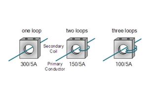
Wound Current Transformer – The transformers primary winding is physically connected in series with the conductor that carries the measured current flowing in the circuit. The magnitude of the secondary current is dependent on the turns ratio of the transformer.

Testing and Quality Control
Oswell maintains the continuous effectiveness of the quality system through annual audits, continuously improves and avoids making the same mistakes, good continuous training methods, strict technological processes, throughout the daily management of all aspects.
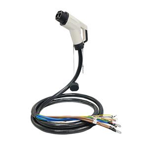
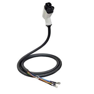
Features ● Output standard DC voltage ● Power-taking CT open-close structure, easy to install and operate ● The power conversion device is fixed with screws, which is easy to install ● Reserved for external energy storage device port
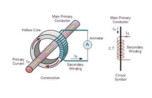
Also known as CTs, current transformers are devices that measure alternating current. They are widely used to measure high magnitude currents. A current transformer essentially lowers (steps down) a high current to a lower, safer level that you can manage properly. It steps down the current to be measured so that you can measure it with an average range ammeter.
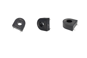
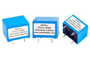
High Precision Current Transformer
● low price ● Various sizes ● Asymmetrical PCB mounting mode ● Single-turn through-core primary winding application ● Applied to occasions requiring high precision and small phase error ● Applied to high-precision measuring devices for current, power and electric energy