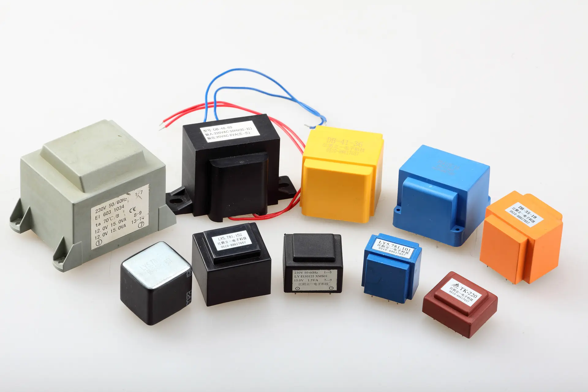
The design of switching power transformer
The design of switching power transformer is divided into three aspects: reduce the loss of switching transformer as far as possible; Minimize leakage of switching transformer; Try to suppress the audio noise of the switching transformer.

1. Reduce the loss of the switching transformer:
① Direct current loss. The DC loss of the switching transformer is caused by the copper loss of the coil. In order to improve efficiency, thicker wires should be selected as far as possible.
(2) AC loss. The AC loss of switching transformer is caused by the skin effect of high frequency current and the loss of magnetic core. High frequency current always tends to flow from the surface when passing through the wire, which will reduce the effective flow area of the wire and make the AC equivalent impedance of the wire much higher than the copper resistance. The penetration capacity of the wire by the high-frequency current is inversely proportional to the square root of the switching frequency. In order to reduce the AC copper impedance, the radius of the wire should not exceed 2 times of the depth that the high-frequency current can reach. The magnetic core loss of switching transformer will also reduce the power conversion efficiency.
2. Reduce leakage of the switching transformer:
In the design of the switching transformer must reduce the leakage to a minimum, because the greater the leakage, the greater the peak voltage range, the greater the drain clamp circuit loss, which will inevitably lead to the reduction of power efficiency. For a switching transformer that meets the insulation and safety standards, the leakage inductance should be 1%~3% of the primary inductance when the secondary is open. It will be difficult to achieve below 1 per cent in the manufacturing process. The following measures can be taken to reduce leakage:
(1) Reduce the number of turns Np of primary winding;
② Increase the width of winding;
③ Increase the height and width ratio of winding;
(4) Reduce the insulation layer between the windings;
⑤ Increase the degree of coupling between windings.
The leakage can be effectively reduced by selecting the appropriate core shape, reducing the number of primary turns and increasing the aspect ratio. Leakage inductance is proportional to the square of the number of primary turns. The core size chosen should be large enough that the primary winding can be wound in two or less layers, which minimizes the primary leakage and distributed capacitance. Do not use the chunky magnetic core, due to its large size, small ratio of height to width, leakage is not suitable for EE, ETD, EI, EC type magnetic core.
Triple insulated wire is a new high performance insulated wire developed in the world this year, this wire has three insulation layers, the middle is the core wire. Its insulation layer is golden polyamide film, called "gold film" abroad; The total thickness of the insulation layer is only 20~100um, but it can withstand the pulse high voltage of thousands of volts. Triple insulated wire is suitable for the cutting-edge technology, national defense field, for the production of miniature motor winding, high frequency transformer winding of miniaturized switching power supply. Its advantages are high insulation strength (any two layers can withstand AC3000V safety voltage), do not need to add a barrier layer to ensure the safety margin, and do not need to wrap insulation tape layer between stages; High current density. The volume of switching transformers winding in it can be reduced by half compared with that wound in enamelled wire. An optimal design scheme of switching transformer is to use ordinary high strength enamelled wire to wind the primary and feedback stages, and use triple insulated wire to wind the secondary, so that the leakage inductance can be greatly reduced, and the volume of the switching transformer can be reduced by 1/2~1/3.
In the process of switching power supply, the distributed capacitance of winding is charged and discharged repeatedly, and its energy is absorbed. Distributed capacitance will not only reduce the efficiency of switching power supply, but also form LC oscillator with distributed inductance of winding to produce ringing noise. The distributed capacitance of the primary winding has a particularly significant influence. In order to reduce the distributed capacitance, the length of wire of each turn should be reduced as far as possible, and the beginning end of the primary winding should be connected to the drain, and a part of the primary winding should be used to play a shielding role, so as to reduce the coupling degree of the adjacent winding.
3. Suppress the audio noise of the switching transformer:
① The attraction between EE or EI magnetic cores can make the two magnetic cores shift. The attraction or repulsion between winding currents can also offset the coil. In addition, EE or EI magnetic core can cause periodic deformation when subjected to mechanical vibration. The above factors will cause the switching transformer to emit audio noise when working, and the audio noise frequency of the switching power supply below 10W is 10~20KHz. In order to prevent the relative displacement between magnetic cores, epoxy resin is usually used as a cement to bond the three contact surfaces (including the center column) of two magnetic cores. But this rigid connection is not ideal, because it does not minimize audio noise, and because there is too much cement, the magnetic core can easily break under mechanical stress. Recently, a special "glass bead" cement has been used abroad to bond EE, EI and other types of ferrite core, and the effect is very good. This adhesive is a mixture of glass beads and adhesive in a ratio of 1:9. It can be cured after being placed in a temperature of more than 100 degrees Celsius for 1 hour.
② In order to prevent the leakage magnetic field of the switching transformer from interfering with the adjacent circuit, a copper sheet can be wrapped around the outside of the transformer. The shielding belt is equivalent to a short circuit ring, which can inhibit the leakage magnetic field. The shield tape should be grounded.


