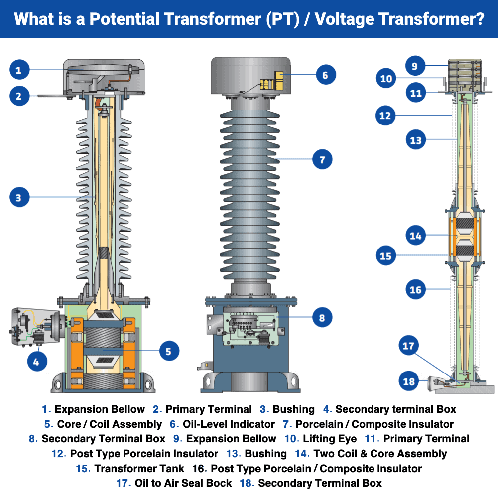
Potential Transformer Construction and working
Potential Transformer Construction
Potential transformer or PT can have the same construction as any normal transformer. It has primary & secondary winding. The number of turns in primary windings is greater than the number of turns in the secondary winding because it is a step-down transformer.

The design & the material used for PT help in achieving greater accuracy. Therefore, the economy of the material being used is not considered important. Here are some of the points that are used during the construction of PT.
The size of the conductor used in windings is large.
The windings are wounded co-axially to reduce the leakage reactance.
The shell-type structure is used for low voltages
The core type structure is used for high voltages.
The high voltage primary windings are divided into sections to reduce the insulation cost.
The windings are also covered with varnish cambric to reduce the insulation cost.
Hard fiber is used as a separator between the coils.
The core is made of high-quality material to have low flux density.
The core material allows it to work on a low magnetizing current.
The PT’s terminals are designed in such a way that the change in voltage ratio with the load is minimal.
The phase angle shift between the input & output must be minimum with load variation.
For high voltage, an oil-filled transformer is used to increase the insulation & oil-filled bushing is used to connect with a high voltage line.
Potential Transformer Working
The working of PT is similar to any conventional transformer. The electrical energy is transferred between the primary & secondary winding through magnetic induction.
The alternating voltage at the primary generates alternating magnetic flux in the transformer core. Since both windings use the same core, this alternating flux induces a voltage in the secondary winding. Thus current starts to flow in the secondary winding.
Since the primary has a greater number of turns compared to fewer secondary turns, the voltage induced in the secondary is very low. The secondary voltage is measured by using a standard low voltage voltmeter. Using the turn ratio equation of the transformer, we can calculate the primary voltage.
VP/VS = NP/NS
Where
VP = Primary Voltage
VS = Secondary Voltage
NP = No. of Turns in Primary
NS = No. of Turns in Secondary
Since the voltmeter has very high impedance, very low current flow through the secondary windings of the PT. for the same reason, the PT has very low VA ratings around 200VA.


