Working principle of high frequency transformer
Working principle of high frequency transformer
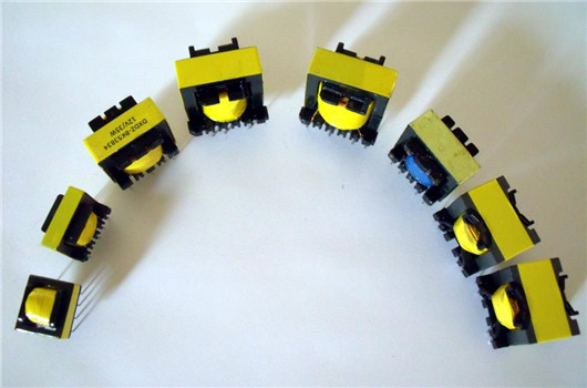
The high frequency transformer is the most important part of the switching power supply. The switching power supply generally uses a half-bridge power conversion circuit. When working, two switching transistors are turned on in turn to generate a 100kHz high-frequency pulse wave, and then the high-frequency transformer is used to step down and output low-voltage alternating current. The ratio of turns determines the output voltage. The three most conspicuous high-frequency transformers in a typical half-bridge transformer circuit: the main transformer, the drive transformer and the auxiliary transformer (standby transformer). Each transformer has its own measurement specifications in the national regulations, such as the main transformer, as long as it is For power supplies above 200W, the core diameter (height) must not be less than 35mm, while the auxiliary transformer, when the power supply power does not exceed 300W, the core diameter of 16mm is sufficient.

A transformer is a device that transforms AC voltage, current, and impedance. When an AC current is passed through the primary coil, an AC magnetic flux is generated in the iron core (or magnetic core), causing a voltage (or current) to be induced in the secondary coil.
The transformer is composed of an iron core (or magnetic core) and a coil. The coil has two or more windings. The winding connected to the power supply is called the primary winding, and the remaining windings are called the secondary winding.


