Company News
-
2005-2023
Application range of brass terminal
Brass terminals are commonly used connectors in electronic components, widely applied in various electronic devices.
-
2804-2023
OSWELL has a perfectly end at 2023 Hong Kong Electronics Fair (Spring Edition)
The first-ever InnoEX, along with the Hong Kong Electronics Fair (Spring Edition) has opened at the Hong Kong Convention and Exhibition Centre at 12-15/04/2023, attracting a large number of professional visitors to stop, consult and experience.
-
2104-2023
A measurement method for parallel resistance of solar cells
A measurement method for parallel resistance of solar cells 1. The larger the series resistance is, the more the short circuit current drops, and the more the filling factor will accordingly; The smaller the shunt resistance, the greater the current, the more the open circuit voltage drops, and the more the fill factor drops.
-
1904-2023
How to calculate the multiple of the ammeter after using the shunt
Motor test measurements usually require ammeters to be equipped with multiple shunt units to solve the problem of ensuring the desired measurement accuracy over a larger measurement range. At this point, the rated voltage drop of all shunt used must match that of the ammeter (e.g. 75 mV).
-
1704-2023
Note the following when connecting the current transformer
Note the following when connecting the current transformer: 1) The secondary side of the CT must not be open when used. When disassembling the meter or relay during use, short circuit the secondary side beforehand. During installation, wiring should be reliable, and fuses should not be installed on the secondary side; 2) One end of the secondary side must be grounded.
-
0704-2023
Rogowski coil measurement schematic
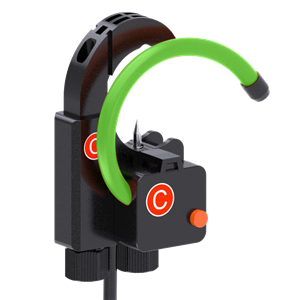
A rogowski coil is a circular coil evenly wound around a non-ferromagnetic material. The output signal is the derivative of the current with respect to time. Through a circuit integrating the output voltage signal, the input current can be truly restored. The coil has the characteristics of real-time current measurement, fast response speed, no saturation, suitable for AC, especially high frequency current measurement.
-
0504-2023
Current transformer and rogowski coil
-
0404-2023
common mode choke
Common-mode choke: In the common filter, usually only one common-mode choke is installed, and the leakage inductance of the common mode choke is used to generate an appropriate amount of differential mode inductance,
-
0204-2023
DR Inductor
The skeleton of the I-inductor is supported by the winding of the copper coil. I-inductance is one of the attributes of an electronic circuit or device.


